TSP1 Dev Kit User Guide#
Introduction#
Congratulations on receiving your Time Series Processor 1 (TSP1) development kit! We have worked hard to make sure that your experience is the best that it can be.
The TSP1 development kit comes preloaded with an English automatic speech recognition (ASR) state space model (SSM) that highlights the TSP1’s principal advantages:
Fully on-device processing
Real-time data stream management
High transcription accuracy
Extremely low power
Low latency
Power can be measured directly to verify power consumption in real usage scenarios.
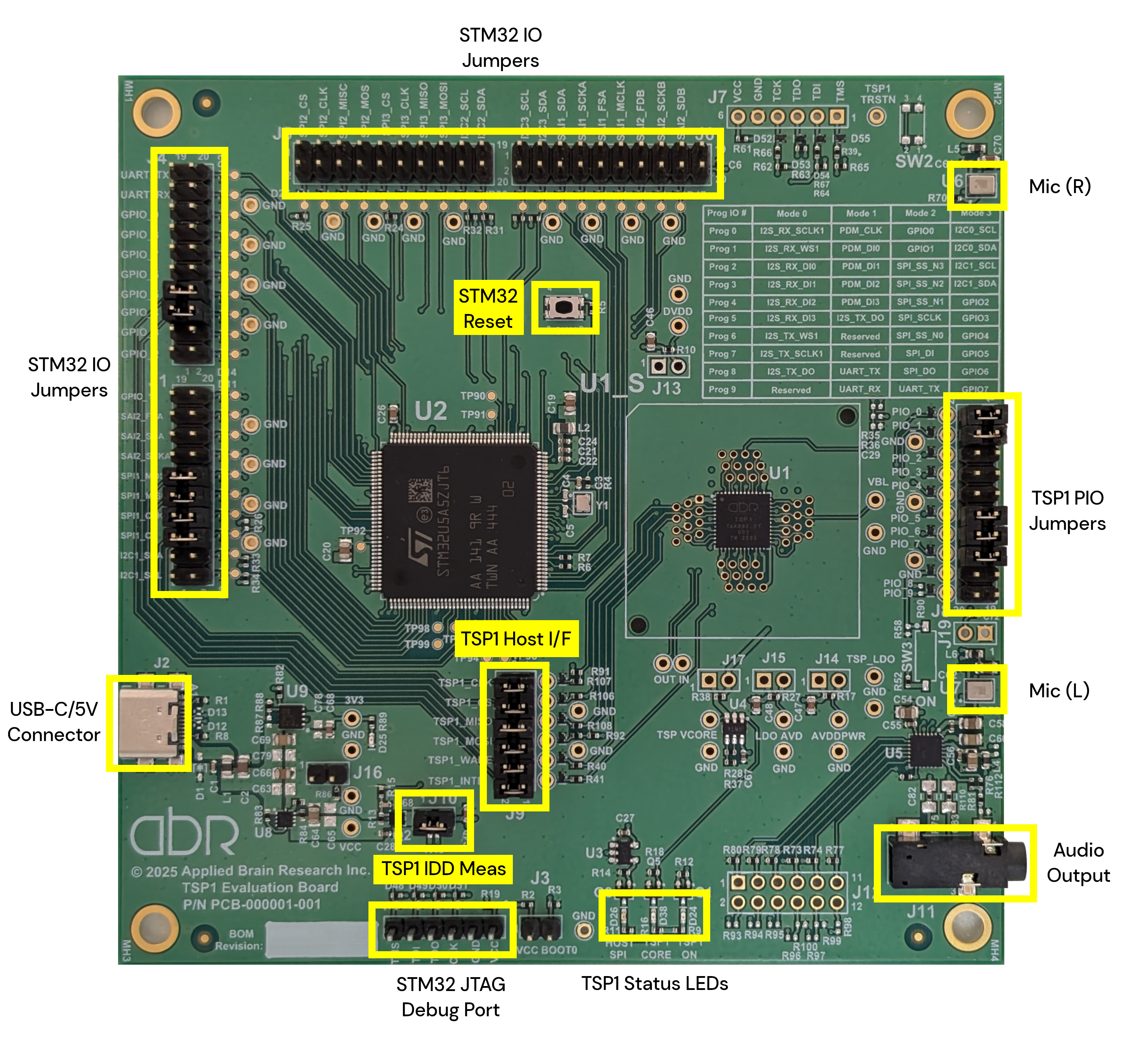
Fig. 2 TSP1 Development Kit PCBA#
Support and Resources#
For software downloads and other resources for your TSP1 dev kit, please visit our developer portal.
If you encounter an issue during your use of the TSP1 development kit, please reach out to us through our support form.
Hardware Overview#
The TSP1 development kit provides a complete platform for evaluating and developing with the TSP1 accelerator chip. This section details the board components, interfaces, and specifications.
Board Layout and Components#
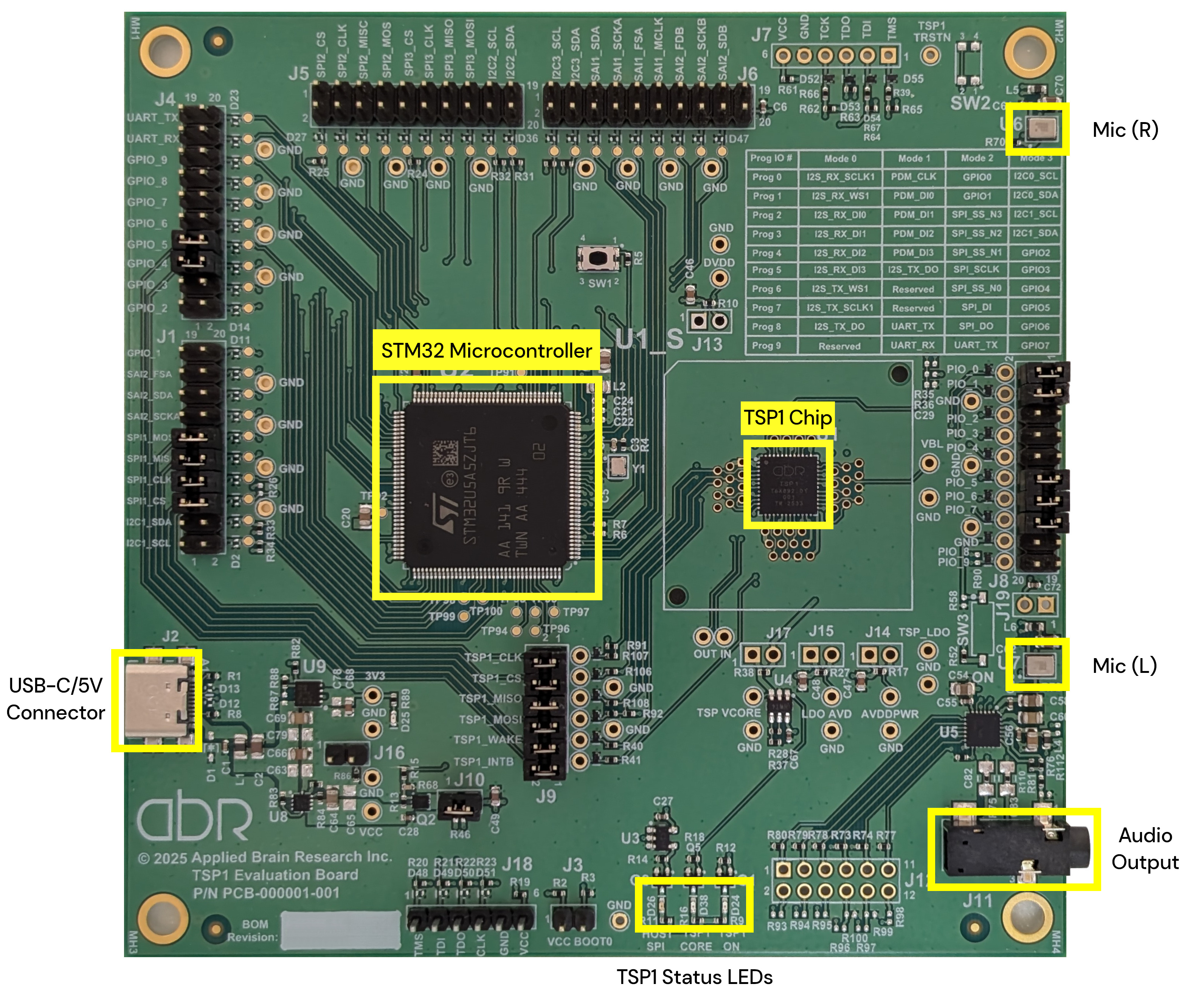
The development board features the following key components:
TSP1 Chip: The AI accelerator chip.
STM32 Microcontroller: Handles board management and interfaces with the host system.
USB-C/5V Connector: Provides power and data from host system.
Onboard Microphones: Two integrated microphones for audio input testing.
Headphone Jack: 3.5 mm jack for audio output testing.
LED Indicators: Status LEDs provide visual feedback on board state.
LED |
Reference |
Color |
Indication |
|---|---|---|---|
TSP1_ON |
D24 |
Green |
VDD supply is active |
TSP1_CORE |
D38 |
Green |
Core VDD is active |
3V3 |
D25 |
Green |
3.3 V regulator is active |
HOST_SPI |
D26 |
Orange |
SPI bus activity (flashes during communication)[1] |
All four LEDs should be illuminated during normal operation, with HOST_SPI flashing when the board communicates with the TSP1 chip.
Connectors and Interfaces#
J2 - USB-C Power Input#
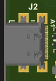
The USB-C port (J2) is the primary interface for power and communication with the host computer. This is the only connection required for normal operation.
Caution
When plugging in a USB cable, hold the USB-C connector to avoid stressing the solder connection to the PCBA.
J8 - TSP1 Programmable I/O Pins#
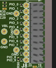
The J8 header provides access to the TSP1’s programmable I/O pins. To connect PCBA components to the TSP1, install a jumper to short the pins as listed in the table below. To connect other I/O devices to the TSP1, install a jumper wire directly to the left (even-numbered) header pins.
TSP1 Signal |
J8 Header Pins |
Function |
Jumpered by default |
Description |
|---|---|---|---|---|
TSP1_PIO_0 |
1-2 |
TSP1_MIC_CLK |
Y |
PDM clock for microphones |
TSP1_PIO_1 |
3-4 |
TSP1_MIC_D0 |
Y |
PDM data input, stereo L & R |
TSP1_PIO_2 |
5-6 |
TSP1_MIC_D1 |
N |
PDM data input |
TSP1_PIO_3 |
7-8 |
TSP1_MIC_D2 |
N |
PDM data input |
TSP1_PIO_4 |
9-10 |
TSP1_MIC_D3 |
N |
PDM data input |
TSP1_PIO_5 |
11-12 |
DAC_DIN |
Y |
I2S audio data out |
TSP1_PIO_6 |
13-14 |
DAC_FSYNC |
Y |
I2S word select out |
TSP1_PIO_7 |
15-16 |
DAC_BCLK |
Y |
I2S bit clock out |
TSP1_PIO_8 |
17-18 |
TSP1_UART_TX |
N |
UART transmit (alternative: I2C data) |
TSP1_PIO_9 |
19-20 |
TSP1_UART_RX |
N |
UART receive (alternative: I2C clock) |
The default configuration connects the TSP1 to the onboard PDM microphones for audio input and the onboard DAC and amplifier through I2S for audio output.
J9 - TSP1 Host Interface#
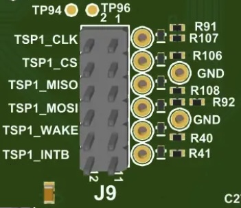
The J9 header provides access to the TSP1 chip’s host interface. To connect to the onboard STM32 controller, all pin groups below must be shorted with jumpers. To connect to an off-board controller, remove all jumpers and install jumper wires between an SPI bus initiator and the right (odd-numbered) header pins.
Signal Name |
J9 Header Pins |
Jumpered by default |
Description |
|---|---|---|---|
TSP1_CLK |
1-2 |
Y |
Host SPI clock |
TSP1_CS |
3-4 |
Y |
Host SPI chip select |
TSP1_MISO |
5-6 |
Y |
Host SPI data in (from TSP1) |
TSP1_MOSI |
7-8 |
Y |
Host SPI data out (to TSP1) |
TSP1_WAKE |
9-10 |
Y |
Wake signal to TSP1 |
TSP1_INTB |
11-12 |
Y |
Interrupt from TSP1 (active low) |
J10 - Main Power Measurement#
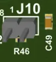
The J10 jumper allows you to measure the TSP1 chip’s power consumption. See Measuring Power Consumption for the measurement protocol.
Configuration |
J10 Pins 1-2 |
Description |
|---|---|---|
Normal Operation |
Shorted (default) |
TSP1 receives power (1.8 V, 3.3 V) from the board |
Power Measurement |
Open |
Insert low-impedance ammeter between pins to measure current |
Warning
Always remove the USB cable providing power before removing or installing jumpers on J10.
J11 - Audio Output#
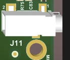
The J11 connector provides audio output for connecting headphones. The onboard audio DAC and amplifier drive this output.
Note
The output requires a load impedance of at most 10 kΩ. Low-impedance speakers (4–8 Ω) draw more current than the amplifier is designed to provide. High-impedance line-level inputs are not supported.
Caution
When plugging in an audio cable, hold the headphone jack to avoid stressing the solder connection to the PCBA.
U6 and U7 - Onboard Microphones#


The board includes two MEMS PDM (Pulse Density Modulation) microphones for stereo audio input:
U6: Right channel microphone
U7: Left channel microphone
These microphones connect to TSP1_PIO_0 (clock) and TSP1_PIO_1 (data) via the J8 header. They are used for automatic speech recognition (ASR) applications and testing.
Configuration Jumpers#
The board includes several configuration jumpers for advanced usage scenarios. The default settings support ASR and TTS applications.
J3 - STM32 Reflash Mode (VCC_BOOT0)#
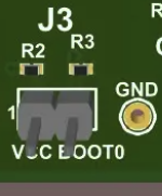
The J3 jumper controls the boot mode of the onboard STM32 microcontroller, allowing firmware updates.
Configuration |
J3 Pins 1-2 |
STM32 Boot Mode |
|---|---|---|
Normal Operation (default) |
Open |
Boot from internal flash (normal operation) |
Reflash Mode |
Shorted |
Boot from USB (firmware update mode) |
To reflash STM32 firmware:
Install a jumper block on J3 (short pins 1-2)
Connect the board to your computer via USB
Use STM32CubeProg to upload new firmware
Remove the jumper block from J3
Press the MCU Reset button (SW1) or power cycle the board
The STM32 will now run the new firmware.
Warning
Incorrect firmware will render the board non-functional.
J16 - I/O Power Selection (1.8 V vs 3.3 V)#
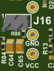
The J16 jumper selects the I/O voltage level for the TSP1 chip and peripheral components (microphones, DAC).
Configuration |
J16 Pins 1-2 |
Description |
|---|---|---|
1.8 V (default) |
Open |
TSP1 I/O powered at 1.8 V (standard operation) |
3.3 V |
Shorted |
TSP1 I/O powered at 3.3 V (for 3.3 V peripherals) |
Default: Open (1.8 V operation)
Note
Voltage level affects the power consumption of the TSP1. For lowest power consumption, use the default 1.8 V configuration.
When to change: Only modify this setting if you are connecting external 3.3 V peripherals that are incompatible with 1.8 V signaling. The onboard microphones and DAC support both voltage levels.
Warning
Changing the I/O voltage may affect compatibility with onboard components. Ensure all connected peripherals support the selected voltage level before making changes.
Buttons and Switches#
SW1 - MCU Reset Button#
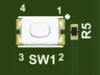
The SW1 button resets the onboard STM32 microcontroller and the TSP1 chip.
Power and Thermal#
Power Requirements#
The TSP1 development board is powered via USB-C (J2) and requires:
Input voltage: 5 V DC via USB-C
Typical current: Varies by workload (see power measurement section)
Maximum current: Depends on TSP1 activity and peripheral usage
No external power supply is required. A standard USB-C cable and port provide sufficient power for all board operations.
Thermal Considerations#
The board operates within standard commercial temperature ranges:
Operating temperature: 0 °C to 70 °C ambient
Storage temperature: −20 °C to 85 °C
The TSP1 chip and STM32 microcontroller are designed for natural convection cooling. No active cooling (fans, heatsinks) is required for normal operation.
Measuring Power Consumption#
You can measure the TSP1 chip’s power consumption using the J10 probe point.
Note
The J10 probe point measures TSP1 chip power consumption, which is the relevant figure for system integration. Measuring current draw at the USB connection will show higher values due to losses in the board’s linear voltage regulators.
Equipment needed:
Multimeter with current measurement capability in mA range
Jumper wires or current probe
Optional: Oscilloscope for dynamic power measurements
Procedure:
Power down the board: Disconnect the USB-C cable
Remove the J10 jumper: Take out the jumper block from J10 (pins 1-2)
Connect ammeter: Connect your ammeter between J10 pins 1 and 2
Pin 1: Power supply from regulators
Pin 2: Power to TSP1 chip
Set ammeter to DC current mode (mA range, e.g. 200 mA setting)
Power up: Connect the USB-C cable to power on the board
Measure current: Read current consumption from your ammeter
Idle: TSP1 in low-power state
Active: TSP1 processing audio (ASR) or generating audio (TTS)
Peak: Maximum current during intensive operations
Calculate power: Measure voltage across the TSP1 power pins (typically 1.8 V core, 1.8 V/3.3 V I/O)
Power (mW) = Voltage (V) × Current (mA)
Power down and restore jumper: When finished, disconnect USB-C, remove ammeter, and reinstall the J10 jumper block
Note
The expected current draw for ASR applications running at 1.8 V is approximately 20 mA.
Warning
Always disconnect the USB cable before removing or installing the J10 jumper. Operating the board with J10 open (no jumper or ammeter) will prevent the TSP1 from receiving power.
Command Line Interface#
This section describes the TSP Command Line Interface (CLI) application and how it is used to interact with the development board.
System Requirements#
The TSP CLI application runs on a wide range of operating systems and has negligible system requirements.
Installation and Setup#
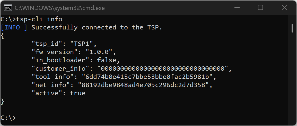
Windows#
Right-click the downloaded
.zipfile in Windows Explorer and select “Extract All…”Choose an extraction location (creates folder
tsp-<version>)Open Command Prompt: Press Windows + R, type
cmd.exe, press EnterNavigate to the extracted folder using
cdRun
tsp-cli infoto verify installation
Note
The TSP CLI is compatible with PowerShell,
but these instructions target the cmd.exe shell.
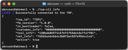
macOS#
Double-click the downloaded
.tar.xzfile to extract itExtraction creates folder
tsp-<version>in the same locationOpen Terminal.app from Applications > Utilities
Navigate to the extracted folder using
cdRun
./tsp-cli infoto verify installation
Note
On macOS the ./ prefix is required unless the CLI location is added to
the PATH environment variable.
Linux#
Extract the downloaded
.tar.xzfile using your file managerOpen a terminal emulator (typically found as “Terminal” in applications)
Navigate to the extracted folder using
cdRun
./tsp-cli infoto verify installation
Note
On Linux the ./ prefix is required unless the CLI location is added to
the PATH environment variable.
Using the TSP CLI#
The TSP CLI provides comprehensive built-in documentation. Use tsp-cli --help
to display available commands, and tsp-cli <command> --help for detailed
information on specific commands.
Command Structure#
Commands follow this general structure:
tsp-cli [global-options] <command> [command-options] [arguments]
Global options (e.g.,
-vfor verbose) precede the commandCommand options (e.g.,
--help) follow the commandSingle-dash options are single letters (
-v), double-dash options are words (--verbose)
Example Usage#
Display TSP connection information:
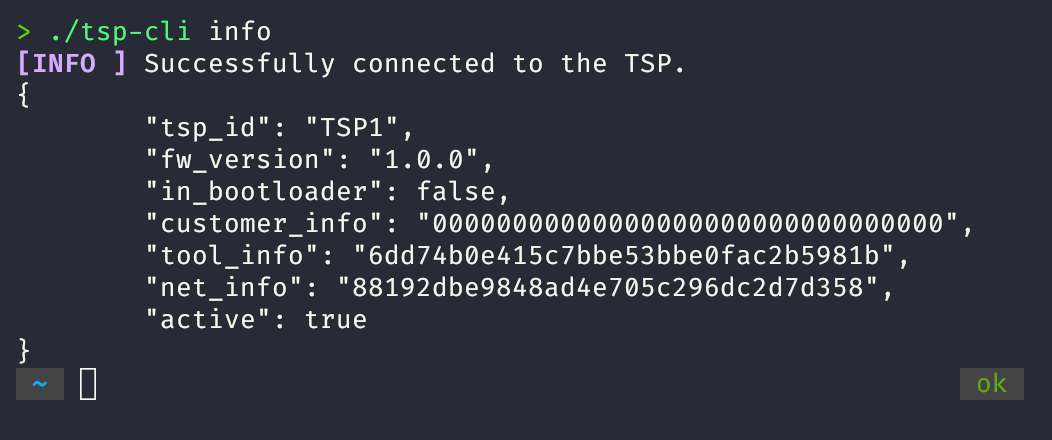
tsp-cli info
Get help for the asr command:
tsp-cli asr --help
Command Reference#
Use tsp-cli <command> --help for complete documentation.
tsp-cli asr - Automatic Speech Recognition#
Streams English text from the TSP1 automatic speech recognition (ASR) model to
the command line. Use the --causal option for lower latency (120 ms) at the
cost of reduced accuracy, or the default non-causal mode for higher quality with
~1 second streaming latency.
tsp-cli info - Connection Information#
Connects to the TSP1 and displays network information as JSON, including TSP ID, firmware version, and operational status.
tsp-cli flash - Download new models#
Downloads a new model onto the TSP and reboots it.
Models are provided as image files with the extension .img.
tsp-cli flash model.img downloads model.img to the TSP1 chip.
tsp-cli stream - Connection Information#
Streams data to and from TSP I/O buffers.
Examples for how to use tsp-cli stream with ASR models
can be found in TSP1 ASR Application Notes.
Using the TSP GUI#
The TSP GUI provides a browser-based graphical interface to ASR and TTS models.
To use it, run tsp-gui tool from a terminal window in the same way
that you would run tsp-cli:
./tsp-gui
This command will open up a new browser window to http://localhost:8080. From here, you can see ASR transcriptions, and write text to be synthesized with TTS.
Safety and Handling#
Electrostatic Discharge Protection#
Discharge static electricity from your body before handling the TSP1 development board by wearing an ESD wrist wrap or touching a grounded metal surface. Store the board in an anti-static bag or ESD-safe container when not in use
Handling Procedures#
Do not handle the board while it is powered
Support the board when installing jumpers
Hold USB or headphone connectors when inserting and removing cables
Keep the board in protective packaging until ready for use
Operating Environment#
The board contains MEMS microphones that are sensitive to certain conditions.
Do not clean the board with an ultrasonic cleaner
Avoid exposing the microphones to direct airflow or high-pressure air
Shipping#
Retain the original packaging in case you need to return the board to ABR.
If you need to ship the board and no longer have the original packaging:
Place the board in an anti-static bag
Use foam or padding to prevent movement during transit
Label the outer package with an ESD warning
Troubleshooting#
Quick Reference#
Error Code |
Description |
Section |
|---|---|---|
|
Cannot detect TSP USB Bridge device |
|
|
Cannot communicate with TSP1 chip |
CLI Issues#
The command line window does not stay open#
When starting tsp-cli, the application window opens briefly and immediately
closes.
Cause: The tsp-cli executable is being launched by double-clicking it in a
graphical file explorer (Explorer on Windows, Finder on macOS).
Solution: Launch tsp-cli from a command line window. See
Installation and Setup for OS-specific instructions.
Connection Issues#
ERR_IO_DRIVER: Could not auto-connect to the TSP#
The following error appears when running any tsp-cli command:
[ERROR] Could not auto-connect to the TSP. Double-check that the development board is connected to your computer and recognized as a virtual serial port by the operating system.
[ERROR] Please see the 'TSP1 Development Kit User Guide' for detailed troubleshooting information. (Error code: `ERR_IO_DRIVER`)
Auto-detection of the TSP USB Bridge has failed.
Cause 1: Development board not connected, or USB port/cable is non-functional.
Solution 1.1: Verify the board is connected to your computer. Try a different USB cable and/or port.
Solution 1.2: Verify the TSP USB Bridge is recognized by your OS and manually specify the serial port.
Windows:
Open Device Manager (Windows + R, type
devmgmt.msc, press Enter)In the Ports (COM & LPT) section, locate “USB Serial Device (COMx)”
Double-click the device, navigate to Details tab
Select “Bus reported device description” from the Property dropdown
Verify the value shows “TSP USB Bridge”
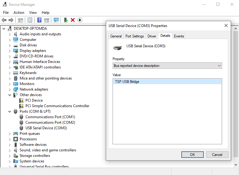
Note the COM port name (e.g., COM3). When running tsp-cli, add
-Userial://COMx after tsp-cli and before the subcommand:
tsp-cli -Userial://COM3 info
Linux:
In a terminal, run
dmesg -w(orsudo dmesg -wif you see “Operation not permitted”)Unplug the board, wait until the LEDs go out, then reconnect it
Look for output similar to:
[ 2930.625878] usb 3-4: new high-speed USB device number 12 using xhci_hcd
[ 2930.749618] usb 3-4: New USB device found, idVendor=0483, idProduct=5740, bcdDevice= 2.00
[ 2930.749636] usb 3-4: New USB device strings: Mfr=1, Product=2, SerialNumber=3
[ 2930.749640] usb 3-4: Product: TSP USB Bridge
[ 2930.749641] usb 3-4: Manufacturer: Applied Brain Research
[ 2930.749643] usb 3-4: SerialNumber: ABR_94AB1P1050004100
[ 2930.777129] cdc_acm 3-4:1.0: ttyACM0: USB ACM device
[ 2930.777148] usbcore: registered new interface driver cdc_acm
[ 2930.777149] cdc_acm: USB Abstract Control Model driver for USB modems and ISDN adapters
Note the device name in the line starting with
cdc_acm(e.g.,ttyACM0)Close the
dmesgwindow
When running tsp-cli, add -Userial:///dev/ttyACMx after tsp-cli and before
the subcommand (note the three slashes):
./tsp-cli -Userial:///dev/ttyACM0 info
Cause 2: Outdated operating system lacking CDC ACM virtual serial port driver (e.g., Windows versions before Windows 10).
Solution 2: Use a supported operating system. See System Requirements.
ERR_INIT: Could not establish a connection with the TSP#
The following error appears after tsp-cli attempts to communicate with the
TSP1:
[ERROR] EventLoop: Too many retries. Giving up.
[ERROR] Could not establish a connection with the TSP. Please ensure that the development board USB bridge firmware is up-to-date, and double-check your SPI wiring or development board jumper configurations. (Error code: `ERR_INIT`)
The TSP USB Bridge was detected, but communication with the TSP1 chip has failed.
Cause 1: Jumper connections on header J9 (between STM32 and TSP1) have been removed.
Solution 1: Power off the board by disconnecting USB. Verify all 6 jumper blocks on header J9 are installed (pins 1-2, 3-4, 5-6, 7-8, 9-10, 11-12). Reconnect and retry.
Cause 2: TSP1 is not powered.
Solution 2: Power off the board. Verify the jumper on J10 is installed (pins 1-2 shorted). Check that the LED indicators show:
TSP1_ON (green) - illuminated
TSP1_CORE (green) - illuminated
3V3 (green) - illuminated
If the LEDs are not lit, there may be a power supply issue. Try a different USB cable or USB port. Reconnect and retry.
Cause 3: TSP USB Bridge firmware is outdated.
Solution 3: Navigate to our developer portal in a web browser: appliedbrainresearch.com/developer. Follow instructions there to update to the latest firmware.
Performance Issues#
Poor transcription quality in the ASR application#
The automatic speech recognition (ASR) application misses words/sentences or produces unreadable output.
Cause 1: Speech volume too high or low, microphones obstructed or otherwise not able to record clear speech.
Solution 1: Speak 40–60 cm from the board at natural conversational volume. Face the microphones (U6 and U7) on the board. Speaking too close (<10 cm) causes distortion; speaking too far (>2 m) or facing away reduces clarity.
Cause 2: Excessive ambient noise or direct airflow on microphones.
Solution 2: Speak in a quiet environment. The onboard microphones are omnidirectional and unprotected, making them sensitive to background noise (other voices, fans, machinery) and direct airflow.
Cause 3: Running in low-latency “causal” mode.
Solution 3: Remove the --causal parameter to run in higher-latency
“non-causal” mode for improved accuracy.
Cause 4: Speaking a language different from the pre-programmed ASR model.
Solution 4: TSP1 Dev Kit boards are pre-provisioned with an English ASR model. Speaking other languages will not produce recognizable output.
Glossary of Terms#
- ASR
Automatic Speech Recognition. The process of converting spoken language into text.
- Causal mode
An ASR processing mode that uses only current and past audio data for speech inference, resulting in lower latency (120 ms) but reduced accuracy.
- DAC
Digital-to-Analog Converter. A component that converts digital audio signals into analog signals. The TSP1 development board comes with an I2S DAC chip with integrated amplifier for driving headphones.
- Development kit
The TSP1 development board (PCBA) with integrated USB interface, microphones, and supporting components.
- ESD
Electrostatic Discharge. The sudden flow of electricity between two electrically charged objects, which can damage sensitive electronic components.
- I2S
Inter-Integrated Circuit Sound. A serial bus interface standard for connecting digital audio devices, used for transmitting audio data from the TSP1 to the DAC.
- Jumper
A small connector that bridges two pins on a circuit board header to configure hardware settings or connect board components.
- Latency
The delay between input to a system and the corresponding output.
- Multimeter
An electronic measuring instrument that can measure voltage, current, and resistance.
- Non-causal mode
An ASR processing mode that incorporates approximately 1 second of future audio data as context for speech inference, resulting in higher accuracy at the cost of increased latency.
- PCBA
Printed Circuit Board Assembly. A circuit board with electronic components mounted on it.
- PDM
Pulse Density Modulation. A digital encoding method used by the MEMS microphones on the TSP1 dev kit to transmit audio data as a high-frequency pulse stream.
- PIO
Programmable I/O. Configurable input/output pins on the TSP1 chip.
- Power rail
A voltage supply line that distributes power to components on the circuit board.
- SPI
Serial Peripheral Interface. A synchronous serial communication protocol used for communication between the STM32 microcontroller and the TSP1 chip.
- STM32
The onboard STM32 microcontroller that manages the USB interface and communication between the host computer and the TSP1 chip.
- SSM
State Space Model. A class of machine learning models for processing sequential data.
- TSP USB Bridge
Firmware running on the STM32 that enables communication between the host computer and the TSP1 chip.
- TSP1
Time Series Processor 1, an accelerator chip designed to efficiently process time-series data in real-time. The TSP1 is a co-processor intended to be paired with an application processor in most deployments.